Thermoelectric properties
The laboratory of thermoelectrics is equipped with measurement instruments developed for both low and high temperature physical characterization of thermoelectric materials. Results, combined with the analysis of the atomic structure of the materials, provide a versatile tool for material design aiming for producing highly efficient thermoelectric materials.
Low temperature measurement
The electrical resistivity, thermoelectric power (sometimes known as Seebeck coefficient or thermopower) and thermal conductivity are measured within the temperature range of 3.5 K < T < 310 K using our proprietary measurement system. The measurement itself is realized using close cycle refrigerator, the vacuum is better then 10-4 Pa. Low pressure or remaining exchange gas is necessary to avoid heat exchange between the sample and surroundings. The measuring apparatus is shown on the figure below.
Fig. 1.: Low temperature measurement system.
The low temperature apparatus including the sample arrangement are shown above. Four (Cu or Ag wire) contacts are attached to the rectangular shaped sample, which is placed in a special measurement cell. A steady state DC four-point method is used for the measurement of all thermoelectric characteristics, the well established method based on the detection of residual temperature and voltage offsets is applied. Ag paste used to create the thermal and electric contacts between the Cu(Ag) pads.
The contact topology is implemented as follows: the differential E-type thermocouples, which detect the temperature gradient ΔT, are simultaneously used for the measurement of voltage drop ΔV. The peripheral Cu contacts are used for the electrical current probing the electric resistivity. A small resistance heater is attached to the top side of the sample, its temperature is also monitored in order to determine the thermal radiation losses. A thin insulating paper is placed between the heater and the sample to avoid the short-circuiting between the heater and sample. Thermal contact between the cryostat and copper base of the measurement cell is improved by means of thermal paste (Apiezon).
The evaluated thermoelectric power measured via chromel wires of the E-type thermocouples must be corrected on its own thermoelectric power (Schromel) using simple relation:  . Simultaneously, the thermal conductivity is calculated as
  , where PSample is the effective heat flowing through the sample, A is the cross-sectional area of the sample and ΔT is the temperature difference between the contacts separated by the length L. To realize the measurement at constant temperature (temperature fluctuations <50mK) and minimize thermal losses the low temperature cell is covered with polished Cu hood with a mass of ~300 g, high mass ensuring the temperature stabilization at each measurement step. An additional polished Al based thermal shield screening thermally the Cu hood ensures the minimization of radiation losses at low temperatures as depicted in the figure below.

Fig. 2.: Detailed link between the cryostat (a), sample (b) and are clearly shown and schematic sketch showing the sample arrangement for the measurement (c).
Calibration
The veracious data are necessary in order to correctly evaluate the thermoelectric potential of studied materials. In this context, the superconducting materials with vanished thermoelectric power are suitable tool for determining the accuracy of the measurement. Similarly, the confrontation of the measured thermoelectric power of pure Ni with literature data offers a good opportunity to confirm the relevance of measured thermal characteristics. In the figure below we demonstrate that the characterizing tool fulfills these criteria; in the left panel we note the "utmost" zero thermoelectric power observed in the superconducting state of HTS superconductor, in the right panel we can confront the measured thermoelectric power and resistivity with literature data.

Fig. 3.: Calibration of the low and high temperature measuring cells using superconducting ceramics and pure Ni.
High temperature measurement
The high temperature electrical resistivity and thermoelectric power can be measured within the temperature range of 300 K < T < 1300 K either in air or under inert gas. The principle of the method together with viewgraphs of the measuring apparatus and sample chamber are depicted below. The measurement is based on homemade furnace with precisely controlled temperature and Agilent multi-meter, which scans both the temperatures of S- type thermocouples and thermoelectric voltages. As the thermoelectric voltage is detected using the Pt- wires of S-type thermocouples, the thermoelectric power of Pt must be subtracted from the evaluated thermoelectric power. Finally, let us note that measurement of the thermal conductivity s using the longitudinal geometry is not possible due to parasitic heat exchange.
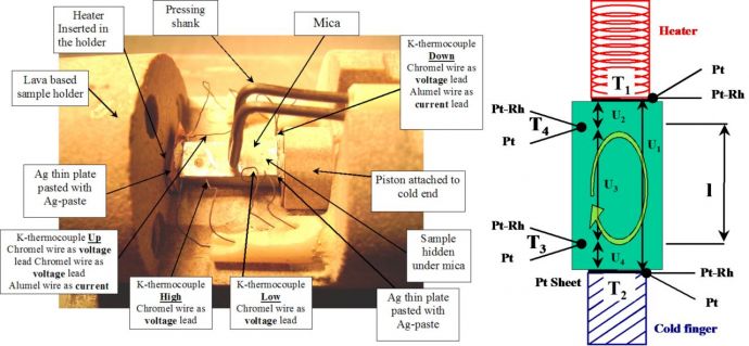
Fig. 4.: The measuring apparatus for the high temperature thermoelectric power and electric resistivity measurement.
Similarly, for high temperature measurement of all thermoelectric characteristics a steady state DC four-point method is used. The realization of the contacts depend essentially on the character of measured material, often Ag paste is used to improve the thermal and electric contacts between the S-type thermocouples and the sample. The contact topology together with stability criterion is clarified in the detail above.
Thermoelectric modules characterization
The testing bench is a useful tool enabling to assess e.g. the thermoelectric parameters of newly developed thermoelectric modules and/or to extract the thermoelectric parameters of commercially available modules considering a simple thermal flow model. The evaluated parameters can be thus confronted with that declared by manufacturer.
The complex measuring facility which enables characterize the power generating thermoelectric modules under a wide range of temperatures (Tcold = 20-80 °C , Thot < 500 °C ) and mechanical loading conditions (P = 0 – 20 MPa) is also available.
In addition to the simultaneous temperature and electrical monitoring of the thermoelectric module, the actual heat flow through the module, heat rate and mechanical load are also monitored. The key component of the testing bench represents the thermally shielded heating block with mechanical loading system and cooler (Fig.5)

Fig. 5.: Thermoelectric module characterization apparatus scheme.

Fig. 6.: Detail of thermoelectric module characterization chamber (left) and the apparatus with nearby accessories (right).
|
|
Laboratory of Oxide Materials
[ Department of Magnetics and Superconductors ] |
 |
|
[ Division of Solid State Physics ] [ Institute of Physics of the CAS ] [ Czech Academy of Sciences ] |
[
Laboratory of
Oxide Materials ]
[ Research ]
[ Thermoelectrics ]
[ Magn. nanoparticles ]
[ Spin Seebeck effect ]
[ Co-perovskites ]
[ Mn-perovskites ]
[ Cu-superconductors ]
[ DMS ]
[ Hexaferrites ]
[ Equipment ]
[ Thermoelectricity ]
[ Diffraction ]
[ MPMS&PPMS ]
[ Synthesis ]
[ DFT ]
[ Publications ]
[ Staff ]
[
Laboratoř
oxidových materiálů ]
[ Krystalochemie ]
[ CHAPL ]
[ Kalvados ]
| Last change: 7. 1. 2019 (K. Knížek) |